MEO FUNCTION IV

How to calculate power of Main Engine (2 stroke engine)?

Power card or PV diagram can be used to measure indicated power in diesel engines. The area within the diagram represents the work done within the cylinder in one cycle.
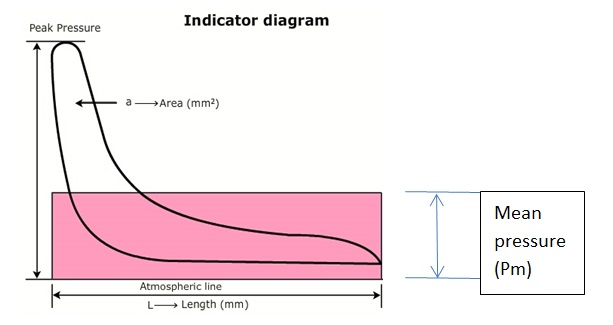
Screenshot (444)

FIG.: Power card

The area can be measured by an instrument known as ‘Planimeter’ or by the use of the mid ordinates rule. The area is then divided by the length of the diagram in order to obtain mean height. This mean height, when multiplied by the spring scale of the indicator mechanism, gives the indicated mean effective pressures for the cylinder. The mean effective or average pressure [Pm] can now be used to determine the work done in the cylinder. Following calculations can be made to the area of indicator diagram to measure indicated power.

Calculations

Area of the indicator diagram = a [mm2]
Average height of the diagram = a [mm2] / l [mm]
Average mean indicator pressure = a [mm2] / l [mm] x k [bar / mm]

or P= ( a / l ) x k [bar]

where k = spring scale in bar per mm

Work done in one cycle = Mean Indicated Pressure x Area of the Piston x Length of stroke = [Pm] x [A] x [L]

To obtain the power of this unit, it is necessary to determine the rate at which work is done,
i.e. multiply work by number of power strokes in one second.

Now, Indicated Power of Unit [ip] = Mean Indicated Pressure [Pm] x Area of Piston [A] x Length of Stroke [L] x Number of Power Strokes per Second [N]

Indicated Power of Unit = Pm L A N

Unit of Final Result

Indicated Power = Pm L A N

= ( a / l ) x k [bar] x L [m] x A [m2] x N [1/s]
= [bar] x [m] x [m2] x [1/s]
= 10N/m2 x m x m2 x 1/s
= 10Nm/s
= 10Joules/s
= 10Watts

Hence, multiply the result obtained from calculating indicated power with 105 and the final unit will be in Watts.

Note 1:  The above equation is valid for 2 stroke engine. For 4 stroke engine, divide N by 2 as there is one power stroke every two revolution of shaft.

Note 2:  On modern engines this diagram can be continuously taken by employing two transducers, one pressure transducer in the combustion space and other transducer on the shaft. Through the computer we can thus get on line indicated diagram and power of all cylinders. The equipment consists of a pressure transducer which screws onto the indicator cock which is connected to the processing unit. A crankshaft position detector is also fitted to the prop shaft or engine flywheel which measures the crank angle to 0.25°.

About the author

Anand Gautam

Anand Gautam is a marine engineer, Graduated from M.E.R.I. Mumbai. He likes to sail onboard ship and is one who is passionate about his job. He loves to share his knowledge, information, and ideas to everyone in a simplified way just for his satisfaction.

2 Comments

Leave a Comment