Navigation

What is the working principle of the autopilot system?

Written by Amit Sharma

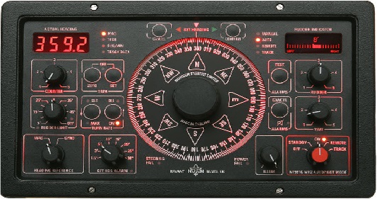
An output from a gyro or magnetic repeating compass is coupled to a differential amplifier along with a signal derived from manual course-setting control. If no difference exists between the two signals, no output will be produced by the amplifier and no movement of the rudder occurs. When a difference is detected between the two sources of data, an output error signal, proportional in magnitude to the size of the difference, is applied to the heading error amplifier. Output of this amplifier is coupled to the rudder actuator circuit, which causes the rudder to move in the direction determined by the sign of the output voltage. The error signal between compass and selected course inputs produces an output voltage from the differential amplifier that is proportional to the off-course error. This type of control, therefore, is termed ‘proportional’ control. As it  has been shown, the use of proportional control only, causes the vessel to oscillate either side of its intended course due to inertia producing overshooting.

PROPORTIONAL CONTROL

The effect on steering when only proportional control is applied causes the rudder to move by an amount proportional to the off-course error from the course to steer and the ship will oscillate on either side of the required course line.

DERIVATIVE CONTROL

The rudder is shifted by an amount proportional to the rate of change of ship’s deviation from the course. The ship will make good a course which is parallel to the required course and will continue to do so until the autopilot is again caused to operate by an external force acting on the ship.

INTEGRAL CONTROL

There are certain errors due to the design parameters of the vessel which have to be corrected. Data signals are produced by continuously sensing heading error over a period of time and applying an appropriate degree of permanent helm is used for this purpose. The permanent helm acts as mid-ship.

PID CONTROL

The output of the three controls is combined and the net resultant drives the rudder. This type of autopilot is also called as PID Auto Pilot.

       A Proportional–Integral–Derivative Controller (PID controller) is a control loop feedback mechanism (controller) commonly used in industrial control systems. A PID controller continuously calculates an error value as the difference between a desired set point and a measured process variable. The controller attempts to minimize the error over time by adjustment of a control variable, such as the position of a control valve, a damper, or the power supply.

  • P accounts for present values of the error. For example, if the error is large and positive, the control output will  also be large and positive.
  • I accounts for past values of the error. For example, if the current output is not sufficiently strong, error will      accumulate over time, and the controller will respond by applying a stronger action.
  • D accounts for possible future values of the error, based on its current rate of change

With a Proportional, Integral and Derivative steering control system, the oscillation is minimized by modifying the error signal produced as the difference between the selected heading and the compass heading. Figure  shows that a three-input summing-amplifier is used, called a dynamics amplifier, to produce a resultant output signal equal to the sum of one or more of the input signals.

The demanded rudder error signal is inspected by both the differentiator and the integrator. The differentiator determines the rate of change of heading as the vessel returns to the selected course. This sensed rate of change, as a voltage, is compared with a fixed electrical time constant and, if necessary, a counter rudder signal is produced. The magnitude of this signal slows the rate of change of course and thus damps the off-course oscillation.

Obviously, the time constant of the differentiation circuit is critical if oscillations are to be fully damped. Time constant parameters depend upon the design characteristics of the vessel and are normally calculated and set when the vessel undergoes initial trials. In addition, a ‘counter rudder’ control is fitted in order that the magnitude of the counter rudder signal may be varied to suit prevailing conditions

About the author

Amit Sharma

Graduated from M.E.R.I. Mumbai (Mumbai University), After a brief sailing founded this website with the idea to bring the maritime education online which must be free and available for all at all times and to find basic solutions that are of extreme importance to a seafarer by our innovative ideas.

Leave a Comment