- By Astronomical object.
- A Bearing and Sounding
- Running Fix.
By Astronomical object
Six common methods are used :
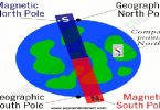
- Latitude by Polaris (Pole Star)
- Latitude by meridian altitude
- Latitude by ex-meridian
- Longitude by meridian passage of the sun
- Longitude by chronometer
- Intercept
Latitude by Polaris (Pole Star)
As the Pole Star is always around the North Pole at radius of 1°, so it is always on or near the meridian passage. The latitude of the observer can be determined. The position line runs in an east-west, or nearly east-west, direction.
Latitude by Meridian Altitude
This method is used to obtain the position line by taking the altitude of the celestial body when it is instantly on the same meridian as the observer’s. In this case, the position line runs in an east-west direction (90°-270°), and coincides with a parallel of latitude.
Latitude by Ex- Meridian Altitude
It is sometimes not possible to obtain the altitude of the celestial body when it is on same observer’s meridian due to cloud, environmental factors, etc. If the altitude of the celestial body can be obtained a few minutes before or after meridian passage, the Ex-Meridian method can be used to reduce the observed altitude to meridian altitude. The latitude of the observer can be determined. The position line runs nearly in an east-west direction.
Longitude by Meridian Passage of the Sun
By knowing that the sun orbits with one completed circle in 24 hours, or 15° for every hour, the observer can determine position at noon by using the chronometer. The advantage of this method is that the DR position is not required.
Longitude by Chronometer
This method is also used to determine the longitude of the observer. The position line runs through the position at DR latitude and observed longitude in a direction perpendicular to the azimuth of the celestial body from the observer.
Intercept
Since it is impractical to draw the large circle of a position circle on the chart, only the part of it in the vicinity of the ship that is perpendicular to the bearing of the body from the ship is drawn. When observing a celestial body, we can obtain its azimuth and altitude. The azimuth is the bearing of the body and the altitude of the body, giving us the zenith distance. As long as the altitude is corrected, the observed zenith distance is the true zenith distance, which is called Observed Zenith Distance or True Zenith Distance. With the D.R. position of the observer at the time of observing, the altitude can be calculated to obtain the zenith distance, which is called Calculated Zenith Distance. The difference between the observer or true zenith distance and the calculated zenith distance is the intercept.
If the true zenith distance is smaller than the calculated zenith distance, then the observer is nearer toward the geographical position of the celestial body compared with the DR position, and the intercept is called TOWARD.
If the true zenith distance is greater than calculated zenith distance, then the observer is further away from the geographical position of the celestial body compared with the DR position, and the intercept is called AWAY.
Bearing and Sounding
This method may be used providing :
- Allowance is made to reduce the sounding to chart datum.
- The depth contours are well defined.
- The contour in question only crosses the position line in one possible place.
- The depth contour crosses the position line at a wide angle
Running Fix
Under some circumstances, such as low visibility, only one line of position can be obtained at a time. In this event, a line of position obtained at an earlier time may be advanced to the time of the later LOP. These two LOPs should not be parallel to each other; remember that the optimal angular spread is 90°. The position obtained is termed a running fix because the ship has “run” a certain distance during the time interval between the two LOPs.
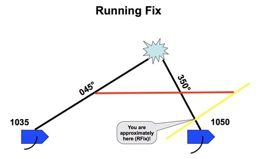
It is more commonly used when only one object is available for bearings and there is no means of measuring the range. In this case there is a planned delay between bearings so that the change in bearing will provide an acceptable angle of cut.


GOOD DESCRIPTIONS OF ALL TOPICS!!
VERY GOOD EFFORT