- Safe pumping procedures are to be provided for ballasting and de-ballasting operations that take into account additional vessel structural stresses that may be involved with conducting ballast water exchange.
- The size of the fixture designated for the overflow is to be verified such that over-pressurization of a ballast tank or pumping equipment, which may lead to structural damage, is prevented. Under pressurization created by a large drop in pressure due to rapid change in the volume of the contents of the tank is also to be avoided by verifying air vent pipes are open and properly sized prior to discharge. Hydraulic calculations verifying the proper sizing of the fixtures are to be submitted for review. Calculations confirming that the capacity of the ballast water tank and the ballast piping are capable of providing ballast water exchange by the flow-through method without the risk of being subject to a pressure greater than design are to be submitted for review. Ballast water carried in double bottom tanks is to be exchanged by the sequential method, unless calculations confirming that pump pressure generated in raising the necessary head of water does not cause excessive internal pressure leading to damage to the vessel.
- Charts and/or tables are to be provided to show the pumping rates, volumes, and time required to exchange ballast water in each tank. In addition, the charts and/or tables are to identify the openings used for release of water from the tank, together with overboard discharge arrangements.
- Arrangements for the examination by the vessel’s crew of sounding pipes, vent pipes and non return devices involved in ballast water exchange are to be provided. Cautionary procedures to be taken regarding the use of air pipes that are not designed for continuous ballast water flow, and weather tight closures (e.g., manholes) which are to be re-secured after flow-through ballast water exchange, are to be provided within the Ballast Water Management Plan and on the charts and/or tables required in item iii) above.
- The circumstances and conditions under which ballast water exchange is not to be undertaken due to adverse weather, design limitations, equipment failures, loss of power or other extraordinary circumstances that could threaten human life or safety of the vessel are to be detailed.
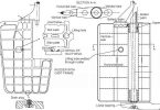
- A flow-through method that has water flowing on the deck is not recommended. The use of collecting pipes, internal overflow pipes or interconnecting pipe/trunk arrangements between tanks is to be used to avoid water flowing on the deck.
- The cautionary procedures related to flooding of deck areas and icing during cold weather conditions are to be identified (for example, the flow-through method is not to be performed in low temperature weather conditions that would result in icing). Where the effect of icing on deck has not been taken into consideration, the Ballast Water Management Plan is to indicate, “The flow-through method is not to be performed in weather conditions that would result in icing.”
- For the flow-through method, it is recommended that the inlet and outlet piping connections be located as remotely from each other as practicable. Aft and fore peak tanks are to be provided with additional pipe work to improve the mixing conditions, unless documentation can be provided to demonstrate adequate mixing. The total cross sectional area of the ballast water discharge pipes on the upper deck is not to be less than two times that of the cross sectional area of the filling/suction pipe. To optimize the ballast water exchange, the ballast water discharge pipes serving the same tank are to be of a different diameter. The discharge pipe located closer to the filling/suction pipe is to have a smaller diameter than the other discharge pipe located further away from the filling/suction pipe. For illustration purposes and as an example, where the filling suction pipe has a diameter of 250 mm, the discharge pipes may be of 200 mm and 300 mm diameter, respectively.
- Where topside and lower hopper side tanks are not interconnected, the scantlings of the hopper and double bottom tanks are normally derived using the head to the top of the tank or two/thirds the distance to the top of the overflow, whichever is the greater. Traditionally, ballast tanks are filled until ballast water overflows. The water pressure at the tank bottom drops immediately due to entrapped air, which reduces the water level in a small diameter overflow pipe. However, the flow-through method will result in a constant high pressure during the long periods required to complete the exchange. Therefore, for flow-through ballast water exchange where topside and hopper side tanks are not interconnected, the scantlings of the tank boundary structure are to be verified using a tank head equivalent to the full distance to the top of the overflow plus the generated back pressure at the maximum flow rate.
- The installation of additional air pipes, access hatches (as an alternative to deck manholes), internal overflow pipes (to avoid overflowing on the deck), or interconnecting pipe/trunk arrangements between tanks, where applicable and possible, may be considered.
Related Searches
- What Is Ballast Water Management( BWM) Convention?
- What are methods of Ballast Water Exchange?
- What is Sequential Method of ballast water exchange and factors taken into account?
- What is Dilution Method of ballast water exchange and factors taken into account?
- What are regulations for Ballast Water Exchange(BWE) to take place?
- Which ships BWM ( ballast water management) Convention is applicable to?


