Destructive tests
Destructive tests aim to examine the mechanical, chemical, and metallurgical properties of a weldment by breaking, deforming, or chemically processing test specimens removed from a welded joint. These tests are considered to be a direct method of examining the qualities of the weldment.
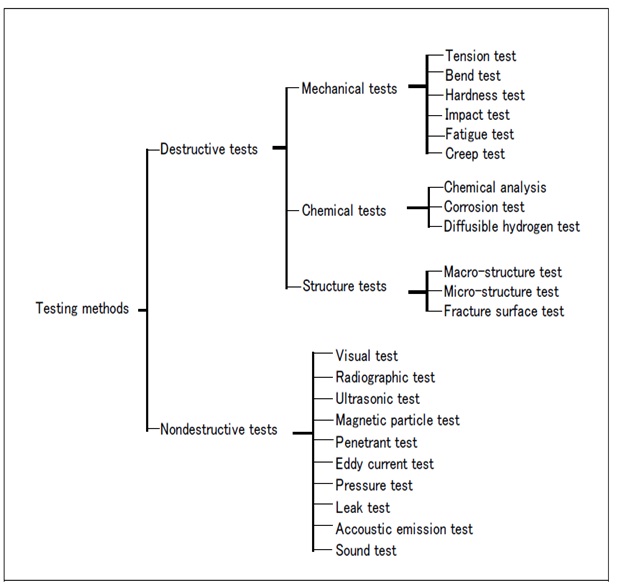
The destructive tests can be classified into mechanical tests, chemical tests, and structure tests.
The destructive tests are often used to confirm whether or not specific welding procedures can produce the required qualities of the weldment. The following sections outline the major destructive tests.
Destructive tests are as follow –
-
Tension test
Tension tests examine yield strength, tensile strength, elongation and reduction in area by stretching a tension test specimen until it ruptures. The tension tests of a weld metal and a welded joint are conducted according to the specification to be followed.
For fillet welds, the shearing strength of fillet joints is examined, using a tension test machine.
-
Bend test
Bend tests examine the ductility of welds and whether they contain welding defects or not.
Bend test specimens are usually removed from butt weld joints so that the weld is perpendicular to the longitudinal axis of the specimen.
In bend tests, three different types of specimens are used, depending on the surface to be tested:
- Face-bend specimens,
- Root-bend specimens, and
- Side-bend specimens.
The bend tests include the roller bend test, guide bend test, and free bend test.
-
Impact test
Metals may be fractured in the ductile mode or brittle mode depending on the environment where the metals are loaded. The fracture of a metal with plastic deformation in standard tensile testing and slow bend testing is considered ductile fracture.
Ductile metals (as judged by tensile or bend tests), however, may fracture with little or no plastic deformation, when subjected to critical testing or service conditions.
This type of fracture is considered brittle fracture. The critical conditions depend on the fracture toughness of the metal. The brittle fracture is considered more dangerous because a high-velocity failure takes place in steel structures.
Three factors markedly influence the brittle fracture behavior of a metal; namely,
- the presence of a notch in the metal,
- the temperature of the metal, and
- the residual
-
Hardness test
The hardness of a weld is the ability to resist indentation or penetration by the point of a material that is harder than the weld being tested.
The hardness test is required to confirm whether or not the weld is hard enough to resist mechanical wearing, or whether or not the weld is ductile enough to stresses, depending on the usage of the weldment.
Four different methods of measuring hardness are in use depending upon the requirement: Brinell, Rockwell, Vickers, and Shore hardness.
In particular, Vickers hardness is most suitable to measure the hardness distribution in a weld.
Non- destructive tests
In order to guaranty the quality of a welded structure, it is indispensable to know what welding defects may or may not exist in the welds. For this purpose, a welded structure could be examined by using a destructive test after fabrication; however, the tested structure becomes out of use if it is fractured by the test.
Therefore, destructive tests are conducted with test specimens, not with a product (except for the sampling test for small products).
Since finished products should never be fractured by a test, it is important to examine the soundness of the welds of the products without breaking them. For this purpose, nondestructive tests are conducted.
Non destructive test are as follow –
-
Visual test (VT)
A visual test is used to examine the appearance, width and thickness of a weld and the welding defects such as undercut, overlap, cracks, pits, and slag inclusions in the surfaces of a weld. It is also used to check whether the throat thickness is as thick as specified and the misalignment is within the allowance.
This test is simple, inexpensive, and is capable of examining many weld zones at one time. Therefore, it is commonly applied to all welds.
-
Radiographic test (RT)
When an accelerated electron hits a target of heavy metal, the radiation emanates. This radiation is a kind of electromagnetic wave. As its wavelength is shorter, its penetrative capacity becomes stronger. This penetrable capacity is used in the X-ray test to detect defects inside welds.
Weld zones can also be examined utilizing the radioactive isotopes (60Co; 192Ir, etc.) that emit γ -rays. These two methods using X-rays and γ -rays are called the radiographic test.
The extent of X-ray penetration varies depending on the kind and thickness of the test material. The radiation intensity changes at where there is a welding defect, reflecting a change in photosensitivity.
The radiation intensity becomes denser at most defects except for tungsten inclusions. Darker portions in the negative film indicate the existence of such defects as blowholes, lack of fusion, lack of penetration, slag inclusions, cracks, and undercut.
A brighter spot in the negative film indicates a tungsten inclusion, because tungsten absorbs the radiation at a high degree. In taking radiophotographs, an Image Quality Indicator (I.Q.I.) and contrast meter are used in order to confirm the quality of radiophotographs.
-
Magnetic particle test (MT)
Irons and ferritic steels can easily be magnetized by a magnet. Therefore, if there is any defect on or near the surfaces of a weldment, the magnetic poles will be developed on both sides of the defect, producing the leaked magnetic flux . When fine magnetic particles are brought near the periphery of this magnetic flux, the particles are magnetized, and the magnetic poles are developed at both ends of each particle.
The magnetic power acts through the magnetic poles of the particles and defective zone. Consequently, the particles are connected each other to develop a particle pattern like a chain.
For the magnetic particles, either a dry powder or liquid suspension powder is used.
By using this method, defects such as cracks and porosity which are open to or close to the surface of a weldment can be detected.
-
Ultrasonic test (UT)
In ultrasonic testing, beams of high frequency sound waves or inaudible, short sonic waves of 0.5-15 MHZ are introduced into a test object to detect and locate surface and internal discontinuities.
A sound beam is directed into the test object on a predictable path, and is reflected at interfaces or other interruptions in material continuity.
The reflected beam is detected and analyzed to define the presence and location of discontinuities.
-
Penetrant test (PT)
The penetrant test uses fluorescent or red penetrant to visualize defects such as cracks and pits that open to the surface of a weld zone. If there is any defect that is open to the surface of a weld, the applied penetrant penetrates into it.
After it has fully penetrated the surface is cleaned with water or solvent depending on the type of penetrant. When a developing solution is applied, the penetrant left in the defect comes to the surface exhibiting an indication pattern.
The pattern is easily identifiable because it is either fluorescent (fluorescent penetrant test) or red (dye penetrant test) depending on the type of penetrant. In this test, even a minute defect can easily be detected.

Leave a Comment